DS9 region file
The tessellation of an image into polygon-shaped geometries — named facets — can be controlled with a DS9 region file. The generic region file format is documented at http://ds9.si.edu/doc/ref/region.html, this pages describes which subset of the region file can be parsed by WSClean and DP3 for the specific use case of tessellating the sky for direction-dependent calibration.
This page provides user documentation. For in-depth technical details, please consult the class responsible for parsing the facet file.
Defining a facet
Facets are specified using “polygons”, where the (ra,dec) coordinates of the polygon vertices are specified sequentially, i.e.
polygon(ra_0, dec_0, ..., ..., ra_n, dec_n)
Please bear in mind:
the
(ra,dec)coordinates should be given in degrees;a
polygoncan have an arbitrary number of vertices;the start and end vertices of the
polygonneed not to coincide;the vertices can be placed in arbitrary order (i.e. clockwise or counter-clockwise);
Adding a text label
Optionally, a polygon can be equipped with a text label and/or a specific
point of interest. The text label should be specified on the same line as the
polygon to which it should be attached and should be preceded by a #.
A valid polygon + label definition thus looks like:
polygon(ra_0, dec_0, ..., ..., ra_n, dec_n) # text="ABCD"
In DP3, this label can be used to refer to the facet. For example, ddecal.modelnextsteps.ABCD=[applybeam] implies that
the beam is only applied to direction ABCD.
Adding a facet point of interest
By default the facet point of interest is the centroid of the facet. To override this behaviour,
a point can be attached to a polygon to mark a specific point of interest. This can be useful to
explicitly mark the position on which direction dependent effects (DDEs) should be evaluated.
Analogous to the polygon definition, the point coordinates are provided in (ra,dec)
in degrees. A point should be placed on a new line, following the polygon
definition, i.e.:
polygon(ra_0, dec_0, ..., ..., ra_n, dec_n) # text="ABCD"
point(ra_A,dec_A)
Only one point can be attached per polygon. In case multiple points were
specified, the last one will be used. So in the following example:
polygon(ra_0, dec_0, ..., ..., ra_n, dec_n) # text="ABCD"
point(ra_A,dec_A)
point(ra_B,dec_B)
the point(ra_A,dec_A) is ignored and point(ra_B,dec_B) will be used.
Example facet file
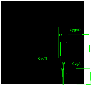
Below a full example of a facet file in DS9 region file format along with its graphical representation is shown. A user-defined point as well as a label is attached to three of the facets, the upper left facet has neither of these. Obviously, the facet definitions serve illustration purposes only and are otherwise impractical, as they are disjoint and do not cover the full image domain.